
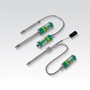
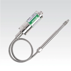
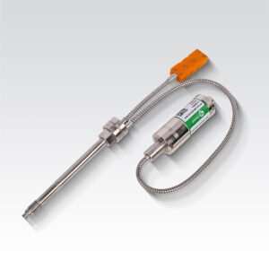
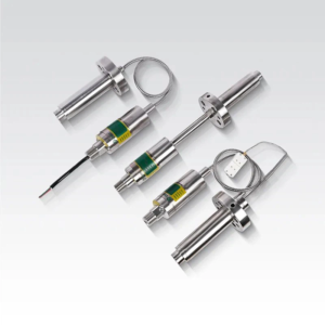
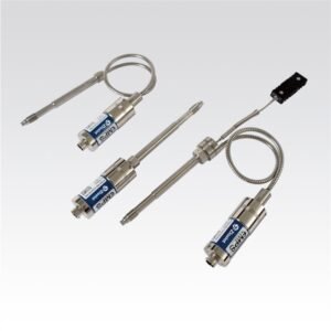
PT170/PT172/PT173 Alloy Filled Green Melt Pressure Transmitter RoHs &SIL2 Certified
The PT170/PT172/PT173 series melt pressure transmitters adopt a patented environmentally friendly alloy filling and an upgraded version of AFT vacuum filling technology, which are safe and non-toxic, have high temperature resistance, and exhibit stable performance.
Introduction
The PT170/PT172/PT173 series melt pressure sensors utilize a patented, environmentally friendly alloy filling and an upgraded version of AFT vacuum filling technology, ensuring safe and non-toxic operation, high temperature resistance, and stable performance.
Application
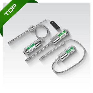
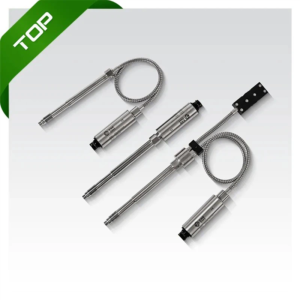
The PT170/PT172/PT173 series melt pressure sensors are suitable for the control of the extrusion process of clean materials such as sheets, composite materials, films, pipes, food packaging, medical packaging, etc.
Product Features
• AFT technology environment-friendly alloy medium filling
• The highest temperature resistance can reach 400℃
• Several diaphragm materials are optional
• With SIL2 & RoHS certificate
• One-key rezero is easy to debug on site
Technical Data
| Pressure Range | 0~35 bar; 0~2000 bar | 0~100 bar; 0~2000 bar | |
| Accuracy | ±0.5%; ±0.25% | ||
| Overload Pressure | 1.5FSO | ||
| Bridge Resistance | 350Ω Wheatstone bridge | ||
| Output Signal | 4-20 mA | 0~10 Vdc, 0~5 Vdc | 3.33 mV/V |
| Power | 9~36 Vdc (Standard 24 Vdc) | 18~36 Vdc | 6~12 VDC (Standard 10 VDC) |
| Load Resistance (Ω) | <(U-9)/0.02 | >10k | |
| Calibration | 80% FSO | ||
| Process Connection | M14×1.5, 1/2 UNF, M18×1.5 | ||
| Insulation Resistance (50 Vdc) | 1000 MΩ | ||
| Diaphragm Material | 17-4PH, Inconel 718, C276 | ||
| Diaphragm Max Temp | 400℃ | ||
| Film Material | TiAIN | ||
| E-connection | 6-pin connector (standard), 8-pin connector (standard) | ||
| Electrical Environment Temp | -20℃~85℃ | ||
| Thermocouple | J Type, E Type, K Type, pt100 | ||
| Protection Degree | IP65 | ||
| Installation Torque | <30Nm | ||
| Filing Material | ATF Alloy-filling | ||
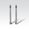
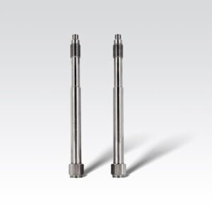
Dimensions


Electrical Connection & Debugging
After the pressure sensor has been installed on the line, the electrical connections must be made as shown in the wiring diagram below.
The PT170/PT172/PT173 series melt pressure transmitter is equipped with an integrated amplification circuit; the calibration process must be the pipeline is heated and the pressure is zero. The zero point is adjusted by activating the autozero function, which is via shorting two pins together (see wiring) or adjusted by twisting the “Z” position screw” at the top of the shell with an object like toothpick,press button 3 seconds to reset zero (please do not touch S” point ).mV signal without this function, can reset zero through the back – end instrument. The output signal is then detected by 80% (see the wiring diagram), and it will provide a signal of a standard 80% measurement.


The cable shall be covered with shielding layer cable; each core wire is about 0.3 mm²; temperature resistance is not less than 105℃; each core wire connection column shall be insulated and protected by heat shrink tube isolation; shield wire shall be connected with plug-in metal; and cable welding should be particularly careful, otherwise it may lead to signal transmission error or damage products. It is recommended to use Ziasiot welded special cable. For excess lines in the cable, each wire should be wrapped separately with insulating tape.

Ordering Guide

Installation & Removal
Installation
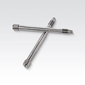
When installing the pressure sensor, the sensor hole should be within the size requirement marked in the following drawing and the assembly accuracy can be checked by testing bolts. Before installing the sensor , first clean the impurities in the hole and between the threads, then the thread of the sensor is coated with heat-resistant slurry, and the screw teeth can be avoided.
The installation force is very important; the installation torque of the sensor can only act on the shaft (hexagon), and do not apply any force to the head of the sensor. The housing should be kept away from high-temperature areas.
1/2-20 UNF / M14×1.5 = Maximum starting torque: 40 Nm M18 x 1.5 = Maximum starting torque: 50 Nm

Removal
The removal of the pressure sensor (transmitter) must be done under heating conditions (plastic melting point). When removing the sensor (transmitter), note that the diaphragm has no contact pressure. The force to unload the sensor (transmitter) must be applied only on the shaft (hexagon) and no force is applied to the head of the sensor (transmitter)


Sensors Cleaning
In order to clean the diaphragm, the sealing surface and thread of the transmitter must have the same temperature as the melting point of the plastic. The diaphragm and sealing surface can be cleaned with soft cloth, and the thread and rigid rod can be cleaned with a steel brush or copper brush. (Do not touch diaphragm surface with steel brush)
Transport And Storage
PT170/PT172/PT173 Series melt pressure sensors (transmitters) are usually packaged separately. At the front thread of the rigid rod, the induction diaphragm is protected by a protective cap. This protective cap should be tightened at any time during storage and only opened during installation.
Reviews
There are no reviews yet.